Quadrature signals, also called IQ signals, IQ data or IQ samples, are often used in RF applications. They form the basis of complex RF signal modulation and demodulation, both in hardware and in software, as well as in complex signal analysis. This post looks at the concept of IQ signals and how they are used.
A pair of periodic signals are said to be in “quadrature” when they differ in phase by 90 degrees. The “in-phase” or reference signal is referred to as “I,” and the signal that is shifted by 90 degrees (the signal in quadrature) is called “Q.” What does this mean and why do we care? Let’s break it down by starting with some basics.
Basics of RF Modulation
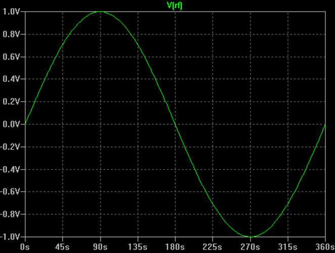
I’ll start with a review simple RF modulation. An unmodulated RF carrier is simply a sinewave as shown below.

The signal can be described as a function of time by the following equation:
V(t) = A * sin (2 * π * f * t + Ф)
where:
A: is the peak amplitude
f: is the frequency
t: is time
Ф: is the phase shift
Information is “carried” by an RF carrier through the process of modulation. The information signal (voice, data, etc.) is used to alter the properties of the RF signal. A simple example is Amplitude Modulation, or AM.
For AM, the information signal is used to alter, or modulate the amplitude of the carrier. Mathematically, it can be represented by changing the constant “A” in the previous equation into some time-varying signal (the information signal):
V(t) = A(t) * sin (2 * π * f * t + Ф)
The information signal, also known as the baseband signal, varies much more slowly with time than the RF signal does. Therefore, to see the effect of the modulation, you need to observe the envelope of the RF signal over a longer time scale as shown below.

In this case, the A(t) signal is a sinusoid. The figure shows how the amplitude of the RF signal follows the sinusoidal A(t) baseband signal.
You can expand on this by recognizing that other properties of the RF carrier can be altered, or modulated, by a baseband signal vs. time. If the frequency is modulated by a baseband signal, you have Frequency Modulation (FM). Similarly, if the phase is modulated you then have Phase Modulation (PM). Thus:
- A(t) is when the amplitude is varied vs. time
- f(t) is when the frequency is varied vs. time
- Ф(t) is when the phase is varied vs. time.
Keep the basic concept of modulation in mind as we tie in the concept of quadrature signals…
Quadrature Signal Concepts
If the phase Ф difference between two sinusoids is 90 degrees (or π /2 radians), then these two signals are said to be in quadrature. An example of this is the sine wave and the cosine wave.

By convention, the cosine wave is in-phase component and the sine wave is the quadrature component. The capital letter I represents the amplitude of the in-phase signal, and the capital letter Q represents the amplitude of the quadrature signal.
Using Quadrature Signals to Modulate
Interesting things happen when you look at adding quadrature signals together.

If I=1 and Q=0, then you would simply have the cosine wave (phase equal to 0). Similarly, if I=0 and Q=1, you would have the sinewave, which is the 90 degree shifted signal.
If both I and Q were equal to 1, then the sum will be a new signal that is shown graphically below.

Note that adding these two equal amplitude quadrature signals together results in a new sinusoid that is phase shifted by 45 degrees.
By now you can see that the amplitude and the phase of the sum of the quadrature signals is a function of the value of I and Q. Therefore, you can create modulated RF signals by varying the I and Q values vs. time. Let’s look at a few examples.
Digital RF Modulation Examples
If Q=0, and I is altered between +1 and -1 over time, you create a Binary Phase Shift Keyed RF signal (BPSK):

The I(t) signal could be a simple digital bit stream. If you have that signal control the gain of the RF sinusoid between +1 and -1, you have created a BPSK signal.
Taking this one step further… If two digital bits are used to control the I and Q values between +1 and -1 over time, then the resulting sum of the quadrature signals can be one of four distinct phases:
- I=+1 & Q=+1 results in 45 degree phase
- I=-1 & Q=+1 results in 135 degree phase
- I=-1 & Q=-1 results in 225 degree phase
- I=+1 & Q=-1 results in 315 degree phase

This is known as Quadrature Phase Shift Keying modulation (QPSK). These are two examples of Quadrature Amplitude Modulation (QAM). The various modulation states for QAM are often shown on a constellation diagram. A constellation diagram is simply a phasor diagram that depicts the amplitude and phase of a signal as a polar plot.

The length of the vector from the origin represents the signal magnitude, and the angle the vector forms with the horizontal axis represents the phase. The four “states” for the QPSK signal described above are shown as the four “+” symbols in the diagram. You’ll also note that the horizontal axis is labeled “I” and the vertical axis is labeled “Q” – because these represent the I and Q component values associated with the signal.
More complex QAM modulations, such as 16QAM, simply have more states. For 16QAM, the I and Q values each can have one of four discrete values, resulting in 16 possible combinations. This results in 16 combinations of amplitude and phase for the RF signal.
Quadrature Signals Everywhere
Using I and Q signals that vary over time to create modulated RF signals is not restricted to digital baseband signals. The I(t) and Q(t) baseband signals can be analog baseband signals too.In fact, in most “digitally” modulated RF applications like QPSK or nQAM, the baseband signals are filtered to slow down the transitions. This is done to limit the resulting bandwidth of the modulated RF signal (fast digital rise/fall times occupy a lot of bandwidth!). These filtered digital signals are effectively analog signals! So, in a more general sense, the quadrature modulation process can be illustrated as shown in this figure:

The general conclusion you can draw from this is that a RF signal with any type of modulation can be created with the appropriate I(t) and Q(t) baseband signals (which in turn vary the amplitudes of the cosine and sine waves that are summed together).
Of course, the same process works in reverse to demodulate an RF signal. By mixing an RF signal with LO (local oscillator) signals in quadrature, I(t) and Q(t) baseband signals can be created.

This is the fundamental basis for most modern RF signal generation and modulation, as well as demodulation and vector signal analysis.
Software Defined Radio (SDR) systems use these concepts extensively because the baseband I & Q signals are often represented as discrete time sampled data. Therefore, digital signal processing (DSP) can be used to literally define the transmitter and receiver characteristics including filtering, modulation and demodulation, AGC, etc. SDR receivers often feature a baseband bandwidth of a few hundred kHz or more, giving the ability to perform a wide variety of functions including “wide” bandscope and spectrogram functions, as well as being able to simultaneously monitor and demodulate several signals of different types at once.
Vector Signal Generators feature a quadrature modulator that accepts I(t) and Q(t) signals which it then uses to amplitude modulate a pair of quadrature sinusoids which are then summed to create the modulated RF output. Many Vector Signal Generators generally include panel jacks where you can connect your own IQ signals. Many include an internal baseband Arbitrary Waveform Generator (AWG) to create the baseband IQ signals.
Modern Vector Signal Analyzers typically feature bandwidths of 25, 40, 110MHz or more. They convert the incoming RF signals into their I and Q components. All of the analysis (spectral analysis vs. time, demodulation, pulse analysis, etc.) is simply different mathematical processing on the same IQ data. Real-Time Signal Analyzers, such as Tektronix RSA5000 and RSA6000 series, have the additional ability to take the “live” IQ data streams and perform real-time processing on the data. This adds the ability to do things like visualize the live spectrum of an RF signal, as well as being able to trigger on transient events that may only be visible in the frequency domain.
Since publishing the above blog, Tektronix is currently offering a free upgrade to 3/6 GHz spectrum analyzers and a free bundle of software applications on mixed-domain oscilloscopes. Check out the details here and save away!