By Christopher Skach
Editor’s Note: This 5-part series of posts will walk you through the fundamentals of radar test and measurement. Here’s the lineup
- Part 1: Radar basics, including continuous and pulsed radar, with a deeper dive into pulsed radar.
- Part 2: Lifecycle of radar measurement tasks, including key challenges in verification and production testing as well as a look at transmitter and receiver tests.
- Part 3: Analysis of radar signals including measurement methods and test setups.
- Part 4: Creating signals that look real to radar.
- Part 5: Tools for measuring modern radar systems.
When it comes to analyzing radar systems, a key challenge is that there is no one size fits all solution. In part, this is because both time and frequency domain information is necessary to characterize radar systems. Pulse analysis is naturally suited to time-domain instrumentation, such as oscilloscopes. Analysis of repetitive pulses, however, requires specialized software to analyze variation in pulse characteristics over many pulses.
Analysis and decoding of pulse modulation is naturally suited to frequency-domain instrumentation such as spectrum analyzers. Simulation of radar systems today requires extensive digital signal processing (DSP) of received signals for pulse compression and Doppler processing. Some processing is most efficiently done in the time domain, some in the frequency domain.
Based on the fundamental strengths of the instruments, selecting the optimum equipment for measuring radar pulses often comes down to the nature of the pulses and whether it fits with the capabilities of available types of test equipment.
Pulse RF carrier frequency is basic. If the available equipment does not cover the frequencies involved, then a frequency conversion device will be required in addition to the fundamental tester. Such a converter may introduce phase and flatness impairments or other distortion. Corrections for these must be an integral part of the measurement system.
Pulse bandwidth is the next consideration. Modern radars are using wider bandwidth pulses, such as faster rise times and wider modulation bandwidths. Many measurements can only properly be measured if the entire bandwidth is captured at once.
A third consideration is modulation. What varied modulations need measurement and what properties of the modulation are critical? Some types of chirped pulses only require that the carrier frequency sweep over the specified range. But others require that the carrier sweep meet a linearity specification. These pulse parameters impact the linearity and dynamic range requirements placed on the test equipment, as well as the phase and frequency flatness of the instrument measurement bandwidth.
Measurements of small signals in the presence of high-power ones, or high-accuracy phase measurements over long time intervals may require a high dynamic range or bit depth of digitization.
Time-domain analysis
The oscilloscope is the fundamental tool for examining varying voltage versus time. It is very well-suited for displaying the shape of baseband pulses. Pulses with very fast transition times or very short duration (sub-nanosecond or shorter) can also be accurately seen on a high-performance oscilloscope using the fast acquisition mode. The mode reduces the dead time between waveform acquisitions, enabling the capture and display of transient events such as glitches or runt pulses. Fast acquisition mode can also display waveform phenomena at an intensity that reflects their rate-of-occurrence.
A useful application for fast acquisition is finding baseband pulse time-domain transient errors. Below you can see that just one single pulse that has a narrower pulse width than even hundreds of thousands of correct pulses. The blue color on the temperature scale for signal persistency is least frequent occurrence, while the red areas are the parts of the signal that are the same every time. In the next image below you can see the single transient glitch in a train of pulses.


One of the most highly developed capabilities of the oscilloscope is triggering. For example, a high-performance oscilloscope’s triggering system can detect transient glitches less than 200 ps wide. Advanced trigger types, such as pulse width trigger, can be used to capture and examine specific RF pulses in a series of pulses that vary in time or in amplitude. Trigger jitter – a crucial factor in achieving repeatable measurements – is ideally less than 1 ps rms.
A mixed domain oscilloscope such as the Tektronix MDO4000C can add a further trigger advantage, providing the ability to simultaneously trigger and acquire signals across multiple channels. This results in time-correlated seamless acquisitions in the analog, digital and RF domains, and provides the ability to observe how the spectral and vector properties of the RF signal vary over time along with the analog and digital signals.
Complementing the advanced trigger system, a fully-automated suite of pulse timing measurements available with Tektronix oscilloscopes can lead to more consistent results. Single-button selection of rise time, fall time, pulse width, and other parameters also simplify the measurement process and save time.
Spectrum analyzer measurements
A traditional swept spectrum analyzer is a simple RF detector that effectively sweeps across a selected span of RF frequencies. This produces a display of the combined RF spectrum of all signals within the selected span of frequencies. There are RF spectrum measurements that can be made manually with markers on a spectrum display but are commonly found as automated routines in most instruments since these can be quite tedious if done manually. Common automated measurements can include occupied bandwidth (OBW), complementary cumulative distribution function (CCDF) and adjacent channel power ratio (ACPR), which is also known as spectral re-growth.
Occupied bandwidth is the most relevant for pulsed radar. Most radars have to meet a specified bandwidth to avoid interfering with RF systems operating on nearby frequencies. This measurement examines the RF spectrum of the signal and locates the highest amplitude value. Then an integration of the power across the spectrum is performed to find the bandwidth occupied by the specified percent of the total power.
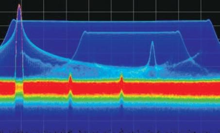
For more capability, however, you’ll want to turn to a real-time spectrum analyzer (RSA). These instruments have an RF conversion section similar to a swept spectrum analyzer. The digitized samples are directly processed by a hardware DSP, and can be simultaneously saved in memory or on a hard disk. This hardware processor performs discrete time transforms into RF spectrum information. This can provide real-time triggering on selected frequency events, or a digital phosphor spectrum display that can discover RF transients and display same-frequency time-sharing RF signals. For example, without phosphor emulation, the screen below would just show the large LFM signal, with the CW signal “popping out” the top on the left. But with phosphor emulation, you can see a second lower power LFM overlapped in frequency. In addition, several single-frequency pulsed carriers and two continuous wave (CW) interferers can be observed.

Like our oscilloscopes, Tektronix RSAs save users time and increase productivity with automated pulse measurements that increase signal detail and measurement repeatability. In some cases, a spectrum analyzer such as the Tektronix RSA7100B will have more advanced capability and can store up to two hours of acquisitions, finds the pulses within it and measures a full set of parameters for each pulse such as timing, frequency and phase parameters, and the results can be further processed to display trends or identify the transmitter.
Many types of techniques are being used in radar systems today with the result that a range of test equipment is required for advanced analysis and troubleshooting. To succeed in today’s world, designers need capable tools to validate designs with advanced scanning methodologies – tools that can handle complex radar baseband, IF and RF signals as well as identify multi-system interference. In addition, analysis in both time and frequency domains is necessary to fully characterize modulated pulse radars. The requires the use of both time-domain instruments such as high-performance oscilloscopes and frequency domain instruments such as real-time spectrum analyzers.
For more in-depth insight on topic, be sure to download our Analyzing Radar Signals Primer.